Design Checklist
 This is the ‘in house’ checklist used to spot problems in drawings sent to us for comment, usually during the clients initial learning period with MPanel. Of course the responsibility for the design stays with the client, but these notes highlight the most common trouble spots.
Form Finding
Is the Model Fully Relaxed?
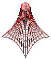
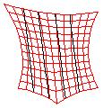
If the model is relaxed for another 100 iterations, does it move at all? Usually if the last relaxation had an error less than 1E-4 you are OK (The last relaxation error is stored in the mesh extended data, shown by the Info tool).
But models with links, used as embedded cables, guys or spars, can creep towards a relaxed position, especially if the link stiffness is set to a high value. So relaxing the model again is the best test. In the drawing you can see mesh movement.
Sufficient Detail in the Model?
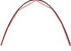
The mesh model is a flat polyface representation of a curved surface. Are there enough faces to keep the modeling error low?
A 12-point polygon approximation to a semicircle has 0.5% length discrepancy. How much error can you accept… perhaps rather less than the expected fabric pre strain, i.e. the compensation value. You can see the error in the drawing.
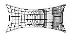
Mesh Polysurfaces Substantially Regular?
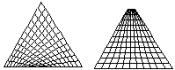
The algorithms that MPanel uses become less accurate when the mesh polyfaces deviate from rectangular. You have to accept some deviation, but avoid meshes that are triangular or have mesh corners that are not at the boundary corners.
The drawing shows poor and good mesh techniques.
Mesh Twisted?
With cone tents, it is possible for the mesh to be twisted as it goes up to the top ring. This can be caused by poor hand stitching, or by moving the bottom corners of a pre drawn model around asymmetrically.
Mesh Even Density?
MPanel will cope with differing mesh densities on multi mesh relaxation’s, but the algorithm used will move the mesh nodes towards even spacing, giving a bow in the mesh junctions. It is better to avoid this complication and aim to keep roughly equal mesh density over the model.
Top Ring Pole Balance Position?
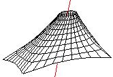
Although the top ring is drawn as a series of fixed points, in practice they are not fixed horizontally, i.e. the top of the pole can move. This is often ignored, but should be looked for in strongly asymmetric designs.
A method of finding the force balance position for the top ring pole is shown in the “Using Links” document. The drawing shows the pole balance position.
Any Mesh Collisions?
These occur either from a loose cable edge, or from hand stitching mesh nodes together. If it’s a cable edge, the procedure to avoid them is shown in the “Deep Catenary” drawing. The drawing shows a mesh collision in a catenary.
Warp/Weft Ratio Reasonable?
If the material is film like then wrinkles will develop when the weft/warp ratio exceeds the Poisson ratio for the material… usually about 3:1. Fabrics loaded along the warp and weft can take a higher weft/warp ratio, but generally the closer the ratio is to 1:1 the less critical the fabric stressing becomes.
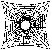
Stress Distribution reasonable?
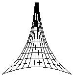
Under normal relaxation, the stress is proportional to the line spacing in the mesh. So the top of the mesh in a cone tent, with a small top ring, has a high longitudinal stress. The drawing shows the line spacing variation in a cone tent mesh.
This is of particular concern to tent designers, who want to use the smallest top ring possible. They can use the constant stress option, which will vary the assumed stress inversely with the line spacing, or reinforce the fabric around the top ring, or use embedded cables to establish the tent shape with a lightly stressed fabric skin.
Paneling
Paneling Errors OK?
When a 3D panel is laid flat the flattening occurs as a shear error. If this figure is too high you should increase the number of panel nodes. For sure, keep the error less than the expected pre strain, ie the compensation value.
Are the Panels Reasonable Shapes?
If the panels have significant center line curvature it may be better to run geodesic seams. If you use geodesics on a heavily curved mesh make sure that the geodesic has enough iterations to reach its correct position.
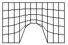
Have the Seams Caught the Corner Detail?
When making geodesic or cross section seams, you must run a seam to any significant geometry, such as mesh corners.
Here the drawing shows seam lines missing a significant bottom corner.
Is the Merging Error OK?
When two adjacent panels are merged, they have to be squashed flat by introducing shear strain. This is reported as the change in the diagonal length of an imaginary square in the fabric.
The shear errors are cumulative. The amount of shearing a fabric can take is not a documented figure, but you can keep it less than the expected pre strain, i.e. the compensation value.
Will the Compensation Create the Correct Fabric Stress?
This is probably the biggest problem. The aim of compensation is to shrink the panels in such a way that the stress assumed during the form finding is put into the structure.
In a straight forward case, with a weft/warp ratio of 2, the panel warp running in the same direction as the mesh warp, and the material having the same stretch values in weft and warp you simply use a compensation of twice as much in weft as in warp.
Loads
Corner Loads Reasonable?
In a cone tent the highest point loads are at the corner anchors. These are the resultant of the cable tensions. If the cable tension ratio is high, the cable tensions may produce unreasonable loads at the corners.
Fabric Stresses in the Working Range for the Fabric?
On a cone tent the warp stress varies inversely to the mesh line spacing, so an estimate should be made of the maximum and minimum bi-axial stresses to check that they are in the working range for the fabric.
Fabric Pre-stress Greater than the Wind Load and Snow Load by a Margin?
The stress change caused by wind pressure or snow load can be estimated from the local principle curvatures on the mesh. The stress change should be reasonably less than the design pre stress.